![<?echo $_SERVER['SERVER_NAME'];?>](/template/twentyseventeen/skin/images/header.jpg)
The digital ground resistance tester adopts the latest digital and micro-processing technology to measure the grounding resistance by 3-wire or 2-wire method. It has a unique line resistance check function, anti-jamming ability and environmental adaptability, ensuring high-precision, high-stability for long-term measurements. Sex and reliability. Applicable to power, post and telecommunications, railways, communications, mining and other departments to measure the grounding resistance of various devices and measure the resistance value of the conductor with low resistance; this meter can also measure the soil resistivity and ground voltage.
The Model MD2571 Digital Ground Resistance Tester has the following features compared to the traditional hand-ground resistance tester:
1. In addition to testing grounding resistance, low voltage resistance, soil resistivity and AC ground voltage can also be tested.
2, using PLL synchronous tracking detection method, and switched capacitor filter, so that the anti-interference ability is extremely strong.
3, abandon the traditional artificial hand-cranked power generation method, without human effort.
4, without the need for manual adjustment of the balance, at a glance the panel touch-button operation, LCD digital display makes measurement very convenient and speed, eliminating the visual error of the pointer instrument.
5. The allowable auxiliary grounding resistance is very large, which ensures better measurement accuracy and higher resolution.
6ã€Apply DC/AC conversion technology, integrate three-terminal button, four-button measurement method into one, use the power supply can be AC, DC dual-use.
Digital Ground Resistance Tester Note:
1. The grounding line must be disconnected from the protected equipment to ensure the accuracy of the measurement results.
2. There should be no stray currents and polarized soil near the measured ground pole.
3. When the soil absorbs too much water after raining, and when the climate, temperature, pressure, etc., change drastically, it cannot be measured.
4. The probe should be far away from large metal bodies such as groundwater pipes, cables, and railways. The current pole should be more than 10m away and the voltage pole should be more than 50m away. If the above metal body is not connected to the grounding grid, the distance can be shortened by 1/2. ~1/3.
5, the connection line should use well-insulated wire, so as to avoid leakage phenomenon.
6. Pay attention to the position where the current pole is inserted into the soil and the grounding rod should be at zero potential.
7, the test should be selected when the soil resistivity is large, such as when the early winter or summer dry season.
8, the test site can not have electrolytic material and decayed bodies, so as not to cause illusion.
9. When the sensitivity of the galvanometer is too high, the voltage probe of the potential probe can be inserted into the soil slightly. When the sensitivity of the galvanometer is not enough, it can be humidified along with the probe water injection.
10. Check the accuracy of the instrument at any time.
Digital Ground Resistance Tester Operation Method:
1, grounding resistance measurement (Figure 1)
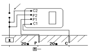
Along the measured grounding stage E (C2, P2) and the potential probe P1 and the current probe C1, they are separated from each other by 20 meters in a straight line, so that the potential probe is in the middle position between E and C, and the probe is inserted into the earth as required. Use dedicated wires to connect the grounding terminals E (C2, P2), P1, and C1 to the location of the probe. Turn on the earth resistance tester's power switch “ONâ€, select the appropriate gear position and touch the key. The indicator light is on, and the value displayed on the meter LCD is the measured resistance value.
2, soil resistivity measurement (Figure 2)

During the measurement, insert four probes along the straight line in the soil to be measured, and make the spacing between the probes equal. The distance between each distance is L. The depth of the probe is required to be L/20cm, and the distance from the probe is C1 and P1 respectively. Each terminal of P2 and C2 is connected with four probes. If the ground resistance meter measures the resistance value as R, then the soil resistivity is calculated as follows: Ф = 2 лrL Ф - soil resistivity (Ω 〃 cm) r - reading of the ground resistance meter (Ω) L - probe and probe The distance (cm) between them and the soil resistivity measured by this method can be approximated as the average soil resistivity embedded in the area between the probes. The probes used to measure the earth resistance and soil resistivity are generally 25 mm in diameter and 0.5 to 1 m long in aluminum alloy tubes or round steel.
3, conductor resistance measurement (Figure 3)

4, the ground voltage measurement and measurement wiring as shown in Figure 1, pull out the C1 plug, E, P1 plug retention, start voltage (EV) file, indicator light, read the meter value is E, P1 AC ground voltage value.
5. After the measurement is completed, press the power “OFF†key to turn off the instrument.
The Model MD2571 Digital Ground Resistance Tester has the following features compared to the traditional hand-ground resistance tester:
1. In addition to testing grounding resistance, low voltage resistance, soil resistivity and AC ground voltage can also be tested.
2, using PLL synchronous tracking detection method, and switched capacitor filter, so that the anti-interference ability is extremely strong.
3, abandon the traditional artificial hand-cranked power generation method, without human effort.
4, without the need for manual adjustment of the balance, at a glance the panel touch-button operation, LCD digital display makes measurement very convenient and speed, eliminating the visual error of the pointer instrument.
5. The allowable auxiliary grounding resistance is very large, which ensures better measurement accuracy and higher resolution.
6ã€Apply DC/AC conversion technology, integrate three-terminal button, four-button measurement method into one, use the power supply can be AC, DC dual-use.
Digital Ground Resistance Tester Note:
1. The grounding line must be disconnected from the protected equipment to ensure the accuracy of the measurement results.
2. There should be no stray currents and polarized soil near the measured ground pole.
3. When the soil absorbs too much water after raining, and when the climate, temperature, pressure, etc., change drastically, it cannot be measured.
4. The probe should be far away from large metal bodies such as groundwater pipes, cables, and railways. The current pole should be more than 10m away and the voltage pole should be more than 50m away. If the above metal body is not connected to the grounding grid, the distance can be shortened by 1/2. ~1/3.
5, the connection line should use well-insulated wire, so as to avoid leakage phenomenon.
6. Pay attention to the position where the current pole is inserted into the soil and the grounding rod should be at zero potential.
7, the test should be selected when the soil resistivity is large, such as when the early winter or summer dry season.
8, the test site can not have electrolytic material and decayed bodies, so as not to cause illusion.
9. When the sensitivity of the galvanometer is too high, the voltage probe of the potential probe can be inserted into the soil slightly. When the sensitivity of the galvanometer is not enough, it can be humidified along with the probe water injection.
10. Check the accuracy of the instrument at any time.
Digital Ground Resistance Tester Operation Method:
1, grounding resistance measurement (Figure 1)
Along the measured grounding stage E (C2, P2) and the potential probe P1 and the current probe C1, they are separated from each other by 20 meters in a straight line, so that the potential probe is in the middle position between E and C, and the probe is inserted into the earth as required. Use dedicated wires to connect the grounding terminals E (C2, P2), P1, and C1 to the location of the probe. Turn on the earth resistance tester's power switch “ONâ€, select the appropriate gear position and touch the key. The indicator light is on, and the value displayed on the meter LCD is the measured resistance value.
2, soil resistivity measurement (Figure 2)
During the measurement, insert four probes along the straight line in the soil to be measured, and make the spacing between the probes equal. The distance between each distance is L. The depth of the probe is required to be L/20cm, and the distance from the probe is C1 and P1 respectively. Each terminal of P2 and C2 is connected with four probes. If the ground resistance meter measures the resistance value as R, then the soil resistivity is calculated as follows: Ф = 2 лrL Ф - soil resistivity (Ω 〃 cm) r - reading of the ground resistance meter (Ω) L - probe and probe The distance (cm) between them and the soil resistivity measured by this method can be approximated as the average soil resistivity embedded in the area between the probes. The probes used to measure the earth resistance and soil resistivity are generally 25 mm in diameter and 0.5 to 1 m long in aluminum alloy tubes or round steel.
3, conductor resistance measurement (Figure 3)
4, the ground voltage measurement and measurement wiring as shown in Figure 1, pull out the C1 plug, E, P1 plug retention, start voltage (EV) file, indicator light, read the meter value is E, P1 AC ground voltage value.
5. After the measurement is completed, press the power “OFF†key to turn off the instrument.
Our company founded in 1998, And we main produce various of WH hollow spindles for coering machine, staple fiber spindles for Two-For-One Twister Machine, spindle for winding machine, Aluminum Bobbin for Covering Machine, pulley Tensioner For Covering Machine. and other parts for Textile Machinery.
We supply of a wide range of machinery for many applications
We provide high quality machines and parts
We offer best after-sales service for customers
We have well experienced team, Engineers available to solve any problem in need.
We persist in the principle of [credit-keep promising,quality-keep upgrading,service-keep improving".Spare Parts
Professional Textile Machinery Spare Parts,Textile Machinery Spare Parts,Hollow Spindle,Textile Machinery
Xinchang Jinxing Machinery , https://www.xcjinxing.com