The first part of the working principle of zirconia oxygen sensor I. Product Description:
The zirconia oxygen sensor uses zirconia ceramic sensors to measure the oxygen potential in various furnaces or exhaust pipes. The corresponding oxygen concentration is calculated from the principle of chemical equilibrium to achieve monitoring and control of the combustion stoichiometric ratio in the furnace to ensure product quality. The measurement components that meet the emission standards of exhaust gas are widely used in the atmosphere control of various types of coal combustion, oil combustion, gas combustion and other furnaces. It is the best measurement method of combustion atmosphere at present, and it has the advantages of simple structure, rapid response, easy maintenance, easy use and accurate measurement. The use of this sensor for combustion atmosphere measurement and control not only stabilizes and improves product quality, but also shortens the production cycle and saves energy.
Second, the oxygen sensor works:
The oxygen sensor is designed using the oxygen ion conductivity characteristics of a stable zirconium dioxide ceramic in an environment of 650°C or higher. Under certain temperature conditions, if there is a different oxygen partial pressure (ie oxygen concentration) in the gas on both sides of the zirconium oxide bulk ceramic, a series of reactions will occur inside the zirconium oxide ceramic, and the oxygen ions will Migration. At this time, stable millivolt-level signals can be measured through the lead-out electrodes on both sides of zirconium dioxide, which we call the oxygen potential. It obeys the Nernst equation: where E is the oxygen potential (mv) output by the oxygen sensor, Tk is the absolute temperature (K) in the furnace, and P1 and P2 are the oxygen partial pressures of the gases on both sides of zirconium dioxide, respectively. . In practical applications, one side of zirconium dioxide is introduced into a gas source (usually air) of a known oxygen concentration, which we call a reference gas. The other side is the measured gas, which is the atmosphere in the furnace we want to test. See Figure 1 for details. The signal output by the oxygen sensor is the oxygen potential signal. We can obtain the relationship between the partial pressure of oxygen and the oxygen potential in the furnace atmosphere through the Nernst equation. When the reference gas is air, it can be expressed as: where E is the oxygen sensor output oxygen potential; Tk is the absolute temperature in the furnace; P02 is the oxygen partial pressure in the furnace. Our oxygen sensor products have a self-heating device, and the general temperature is guaranteed at 700°C, so that the TK value is basically constant, so that the oxygen partial pressure concentration in the furnace can be directly measured by the above formula. In engineering applications, standard gas is used to calibrate the corresponding relationship between oxygen sensor output oxygen potential E and oxygen partial pressure concentration PO2. This method is also currently recognized as the most accurate and most direct calibration method.
The second part of the HMP series oxygen sensor Basic structure of HMP oxygen sensor:
The core component of the HMP oxygen sensor is an imported zirconia oxygen sensor (see Figure 2 for details). The zirconia oxygen sensor comes with an intelligent heating device, which provides a constant voltage control signal to quickly reach the operating temperature, and ensures that the sensor is at a constant temperature. Continuous and stable work. To install the probe, it is necessary to adjust the direction of the guide plate to make the guide plate face the air flow direction as much as possible, so as to form a self-guided flow of gas for detecting the atmosphere. The typical performance characteristics of the imported zirconia oxygen sensor are as follows: zero error: £±0.2 mV; AC resistance (1500 Hz): (700°C) £100 kΩ; (1100°C) £5 kΩ. Response time (700-1300°C): £1 second II. HMP oxygen sensor sampling, maintenance methods:
The HMP oxygen sensor adopts the atmosphere self-conducted flow method to introduce the detected atmosphere. Considering the environmental factors at the project site, a purge purge channel is designed to facilitate the purge work of the sampling guide pipe to avoid dust in the furnace or pipe. , coal ash, oil impurities, etc. block the sampling tube, please refer to Figure 3.
three. Technical performance:
Operating temperature: room temperature ~ 1100 °C; oxygen potential display range: -50 ~ 1240mV; oxygen potential output accuracy: ± 0.5mV; response time: ≤ 1 second; normal use life: ≥ 18 months.
The third part of the oxygen sensor installation is a reasonable installation of the key to ensure the reliable operation of the oxygen sensor, many use problems are caused by improper installation of oxygen sensor, I hope the user must pay special attention to this point, install the oxygen sensor, please consider the oxygen sensor installation Claim:
First, sampling measurement point:
Determining the measuring point is the first job. The following principles should be followed:
(1) The selected measurement point requirement can correctly reflect the required furnace atmosphere to ensure the authenticity of the oxygen sensor output signal and try to avoid the return air dead angle;
(2) The measurement point must not be too close to the combustion point or the nozzle. The atmosphere of these parts is in a violent reaction, which will cause extreme fluctuations in the detection value of the oxygen sensor. Also, do not go too close to gas production equipment such as a fan to prevent the motor from vibrating and damaging the sensor. ;
(3) Avoid placing it in a position where it may collide, so as to avoid collision damage to the probe and ensure the safety of the sensor;
two. Oxygen sensor installation, connection method:
(1) The HMP oxygen probe can be installed horizontally or vertically. Vertical installation is an ideal installation method. Regardless of the method used, the direction of the guide plate of the probe sampling tube should be as close as possible to the direction of the measured gas flow. In the initial installation, the basic direction can be determined by understanding the process. To determine the better guidance direction, you need to turn the direction of the sampling tube after the system is heated and probed, and use a digital multimeter to observe the fluctuation of the output oxygen potential.
(2) The connector used for oxygen sensor installation is a special flange connector. If the user has other types of connectors, this connector can also be replaced as long as the mounting dimensions are the same and the sealing requirements are met. Oxygen sensor special joints, according to the requirements of the need to match the asbestos pad pressure to ensure that the seal, or because the general furnace is negative pressure, where the leakage at the flange joints will affect the measurement accuracy or cause signal fluctuations.
(3) The signal lead of the oxygen sensor is preferably shielded to eliminate interference. The best method is to use two 2-core cables, a 2-core shielded cable to connect the oxygen potential output signal, and a 2-core KVV control cable to connect the probe heating connection; if the on-site condition is not available, a 4-core KVV can be used directly. The cable connects the probe to the oxygen potential signal and the heating end. Aviation plugs are described below (see Figure 4): 1. The heating control signal is connected to probe pins 1, 2 and we have drawn red and yellow two color wires. The control wire can be welded directly; 2. The probe measures the oxygen potential output signal to connect pins 3 and 4. Note that the positive and negative electrodes of the millivolt signal are connected. The white line of the four pins is positive and the black line of the three pins is negative. The signal line can also be directly connected to the lead-out line by butt welding. (4) The standard gas port of HMP oxygen probe is closed when it is normally detected. It is only used when the gas is calibrated. The purge port is connected to the air pump or compressed air line. The purge port inlet is generally controlled by a solenoid valve and other valves. Once it is turned on, the gas is purged through the sampling tube. When the probe is normally detected, the valve is closed and no other gas can enter the sampling tube. In this particular point, the use of factory compressed air to purge the probe must ensure that the compressed air contains no moisture, that is, the compressed air used must be subjected to gas-water separation treatment.
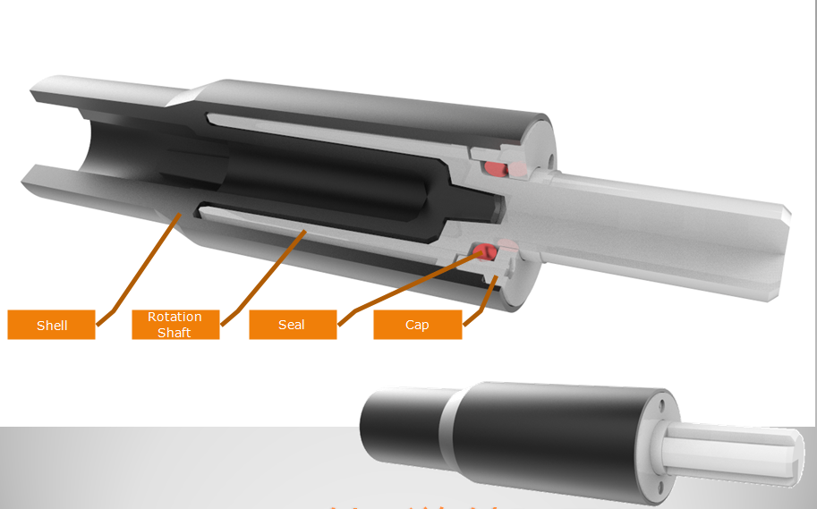
Slim Rotary Damper mainly used for small diameter, long height space. Shaft Damper is used to dampen drives, control speed, and many other applications. Shaft damper are widely used in invisible screens. Shaft damper can make the movement of structures soft, quiet and safe to mitigate the impact, avoid the damage, increase the mechanical life, reduce noise, and improve product quality.

NOTE:
1. Please contact the corresponding product engineer for specific torque products
2. Max. rotation speed: 50r/min
3. Max. circle rate: 5 cycle/min(Clockwise180 °, 180 ° anti-clockwise for 1 cycle)
4. Operating temperature: -10~50℃
5. Storage temperature:-30~80℃

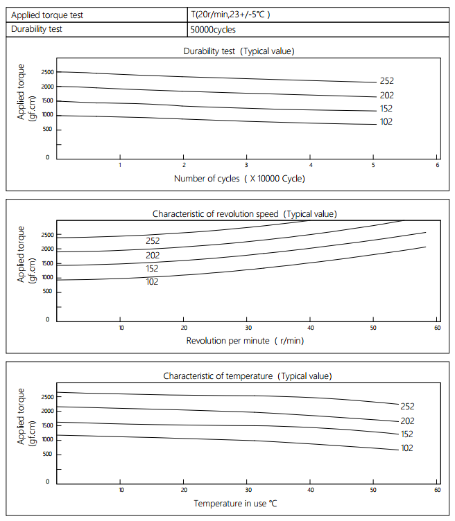
Applied torque: (T)
Test Temperature: 23+/-5℃
Rotating speed:20r/min
Durability test Method:Clockwise 180 °, 180 ° anti-clockwise
Rotating speed: 20r/min
Test Frequency: 1cycle/min
Test Temperature: 23±5℃
Durability test cycle: 50000cycle
Test result criteria: Store in the room temperature for 24 hours or more after the test, recording to the torque T=T±30%T.
Shaft Damper
Shaft Damper,Drive Shaft Damper,Crankshaft Damper,Flexible Shaft Coupling
Shenzhen ABD Equipment Co., Ltd. , https://www.abddamper.com
![<?echo $_SERVER['SERVER_NAME'];?>](/template/twentyseventeen/skin/images/header.jpg)