![<?echo $_SERVER['SERVER_NAME'];?>](/template/twentyseventeen/skin/images/header.jpg)
In recent years, the use of sampling principles, insert installation is more common, measuring only one or more points in the pipeline to calculate the flow rate of the plug-in flow meter, the common characteristics of these instruments are: simple structure, easy installation and maintenance, low prices Reproducibility is good, and it is a high-cost instrument for detecting large-pipe gas flow in an industrial control system. However, its accuracy is generally not high, and it is not suitable for trade settlement that requires accurate measurement. Because the principle is sampling nature, we must first understand the flow velocity distribution in the pipeline in order to correctly select the location and number of detection points.
1 Industrial pipe flow 1.1 The flow velocity distribution in the ever-changing pipe The engineering of all walks of life, starting from its own process requirements, must be installed in a variety of pipe fittings (such as valves, elbows, manifolds, reducers, filters) Wait). Due to their large number of forms and combinations, the resulting velocity distribution within the tube is also very variable and difficult to estimate (Figure 1b). According to RW Miller (author of the US Flow Measurement Engineering Handbook), “The flow rate distribution is the main factor affecting the accuracy of the flow rate. The industrial site has a wide range of accessories and its flow is very complex. It is not only difficult to describe this, but also difficult to simulate in the laboratory. They.†Since most of the flow meters are related to the flow velocity distribution, the flow field of its calibration should be consistent with the flow field of practical conditions, and the coefficient of calibration is of significance. This flow field is recognized as fully developing turbulence, as long as the pipe has a long straight pipe section (Fig. 1a, c).
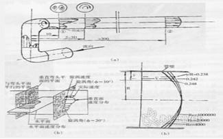
1.2 Fully develop turbulent flow 1.2.1 Formation: Since the actual fluids are all viscous, the fluid in adjacent layers will be driven or confined in the flow process. This action passes through the length of the straight pipe of about 30D (D is the inner diameter of the pipe) and its flow rate. The distribution will not change, such as Reynolds number <2000 for laminar flow, and Re> 4000 for turbulent flow. Most of the industry is turbulent.
1.2.2 Description: Many scientists have conducted extensive tests and descriptions of the full development of turbulence in the past 100 years. Among them, the turbulent flow formula developed by Nikaradse's smooth tube is the easiest. It is approximately expressed as:
V/Vm=(y/R)1/n...(1)
Where: Vm is any point flow rate; Vm is the center of the maximum flow velocity; y is the distance of the flow point from the main wall; R is the radius of the pipe; n is the index and is related to Re.
1.2.3 Average flow rate point y The formula (1) can be used to derive the average flow rate point y of smooth tube full turbulence:
y=R[2n2/(n+1).1/(n+2)]n
From equation (2) we can see that the average flow point in the circular tube depends on three factors: a, the length of the straight section; b, the Reynolds number Re; c, the roughness ε. Therefore, its position is not fixed, unlike some vendors' propaganda, which can achieve ±1.0% flow accuracy by measuring only one point of the pipe flow rate. According to the evaluation of ISO7145, the accuracy can only reach 3% under the conditions of a, b, and c; if the straight section is short, the flow accuracy is even less than ± 5% to 10% (see the 2002 issue 10 ).
1.3 Flow Conditioner
To measure the flow accurately, it must have a long straight pipe length, which is often not met in the actual site. To this end, the International Organization for Standardization has repeatedly recommended the use of more than a dozen types of flow regulators, but I think this is not the best policy, because: 1 increase costs, the price of a flow regulator is no less than a flow meter; 2 need Frequent cleaning, increased maintenance; 3 good flow regulator permanent pressure loss, increased operating costs; 4 easy to plug, even if the partial blockage also changes the velocity distribution, can not improve the accuracy.
2 large-scale pipeline gas flow detection instruments under the premise of China's advocacy to build a conservation-minded society, the large-pipe gas flow detection instrument introduced in this article excludes throttle devices with high pressure loss and high operating costs, and does not recommend over-priced Ultrasonic gas flowmeters only introduce higher cost performance. Take the sampling principle of the plug-in flow meter as an example, according to its point of access can be divided into the following three categories:
2.1 Measure speed All instruments that can measure the flow rate can be used as flow meters. The more common are the following:
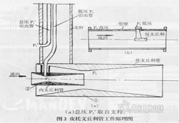
2.1.1 Double Venturi Tubes As early as 40 years ago, the United States Taylar Company has introduced products to the market, called Pitot-Venturi Tube (see country 2a), many domestic thermal power plants have used for imitation of air volume. Measurement, called "small speaker tube." For more than a decade, domestic manufacturers have introduced products based on this principle, known as double venturi tubes (Fig. 2b). The only difference is that the former is taken from the support rod by high pressure, while the latter is taken from the wall of the tube. Under the same flow, the output of the latter is poor. The pressure will be slightly less than the former. The principle is characterized by the use of the outer venturi 1 throat to accelerate the low pressure P2, and the tail of the inner Venturi 2 is placed in the low pressure region of the throat 1. This causes the throat of the 2 to produce a lower low pressure P2', thus the same The larger differential output pressure can be obtained under the flow rate, which is more suitable for the measurement of low-flow gas flow in large pipelines. Because it only measures a little flow velocity, the distribution of velocity in the pipeline has a great influence on it, so the accuracy is low. There is also a Savannah tube on the market. It has a Venturi tube installed in the double Venturi tube in an attempt to obtain a greater differential pressure. When the size is small, the role of the boundary layer will appear, which restricts this acceleration. The antihypertensive effect has produced a negative effect of complex structure and unstable coefficients, and should not be advocated.
2.1.3 Other theoretically, Pitot tube, plug-in vortex and turbine can be used to measure flow. Pitot tubes can be used for industrial field calibration, but they are seldom used as industrial instruments; plug-in vortex streets are not reliable at low speeds and when pipelines vibrate; plug-in turbines have large amounts of maintenance due to rotating parts. In recent years, the market share of these meters has shown a large downward trend. These instrument manufacturers often advertise that their instruments are calibrated in the wind tunnel. In fact, it is only that the calibration flow rate is not the flow rate, and the accuracy of the flow rate cannot reach ±1% of their propaganda.
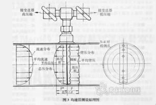
2.2 Measurement of line speed In order to infer the flow rate by measuring the multi-point flow velocity distributed on a line in the pipeline, it is more accurate than the above-mentioned one-point measurement, and the installation is stable and reliable. Detection of large pipe gas flow in industrial control systems is often the preferred instrument, and is typically a uniform flow meter:
2.2.1 differential pressure flowmeter
Circular (Fig. 4A) was launched by Dieterichslan-dardlnc (DSI) in the late 1960s. After use, it was found that Re was between 105 and 106. The dispersion of the flow coefficient K was about ±10% due to Re< At 105 hours, the separation angle of the fluid in the cylinder was 780, and when Re>106, it moved back to 1300. That is, the so-called “resistance crisis†caused instability in the flow coefficient and affected the accuracy of the flow rate. It was eliminated more than 20 years ago.
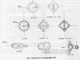
Tug pipe (Fig. 4C): This type of structure was once popular in Western Europe. The detection rod is still basically round, and only a piece of hexagonal milling near the middle back pressure promotes the fluid separation point to be fixed to solve the problem of resistance crisis. There is not only the rhombic-type II back pressure hole blocking problem, but also due to the presence of two different cross-sectional shapes in one detection rod, the fluid pressure distribution will cause lateral flow.
Wing, oval (Figure 4D) The purpose of designing these two cross-section shapes is to reduce the windward resistance. In fact, no matter what type of constant pressure tube is only a few dozen permanent pressure loss, can be ignored, do not have to overestimate, this type of cross-section shape is to reduce its output pressure difference, gaining strength and avoiding losses outweigh the gains. However, there are special circumstances, such as Emerson's use of airfoil cross-section to measure steam flow. Due to the large steam density and high flow rate, the use of airfoil cross-section can be described as local conditions!
Diamond-II fit (Figure 4E): Launched in 1984 by DSI, USA. It is composed of a diamond profile and two triangular profiles. There are 3 to 5 pairs of static pressure holes in the flow direction to adapt to the situation that when the Re changes, the flow velocity distribution changes greatly on the wall surface. This structure is due to the large tolerance of the profile, when the temperature changes, the overflow easily leaks, too tight initial stress is too large to weaken the strength, now gradually eliminated.
Diamond-II (Integral) (Figure 4F): In the early 1990s, it was launched by German IA and Systee one after another, known as Itabar and Deltaflow. The structural feature is to divide the high and low pressure into two cavities with a middle partition. When the required strength is higher, it can withstand more severe working conditions. The temperature can reach as high as 1200°C and the pressure limit can reach 69Mpa. It can also be used for strong corrosive media. Our country can already produce and enter the market, the price is a lot cheaper than the foreign product.
Warhead type (Fig. 4G): Developed in 1992 by U.S. Veris, it is called Verabar. The main feature is that the cross-sectional shape of the detection rod is warhead type, and the head is roughened (roughness x/ks~200). The manufacturer publicizes this to ensure that a turbulent boundary layer forms on the surface of the detection rod, thereby improving the accuracy. Professionals' estimates (for details, see our publication, July 2004, p. 42-44) have less than a one-thousandths of impact, relative to other factors (straight pipe length, pipe diameter, etc.) negligible and need not be exaggerated. Because the static pressure is taken from two sides, the output differential pressure is 30-50% smaller than other equal velocity tubes, which is difficult to apply to low flow velocity and low density applications. In addition, since the pressure tap hole is small, when the fluid contains dust, oil stains, coagulation matter, fibers, etc., it is easy to clog.
The T-type (Fig. 4H) was introduced by DSI in the United States in 2001. It is called Annubar-485. The cross-section of the test rod is T-shaped. It is facing two rows of small holes (or directly with transverse joints) that are densely packed. Since the total pressure extraction pressure hole accounts for almost 85% of the entire diameter, more flow velocity distribution information can be obtained and the accuracy can reach an astounding ±0.75%. This concept was patented in the 1980s and did not enter into practical use. If the length of the straight pipe is insufficient, the turbulence cannot be fully developed. Measuring only the multi-point velocity on the diameter does not reflect the flow velocity distribution of the entire pipe; if the turbulent flow is fully developed, only a few of the flow rates can be fully reflected. No need to use so many measuring points. The manufacturer intentionally avoided the premise of the length of the branch pipe. As for the formation of a high-pressure zone before the total pressure hole, dust will bypass the road. It is also hard to believe: If so, does the windshield wiper still require windshield wipers?
2.2.2 Thermal Averaging Tube Flowmeter: The principle is the same as the one-point thermal model in the previous section, except that there are multiple points in the structure, which reflects the distribution of the velocity at multiple points in the pipeline, so as to calculate the flow.
Comparing the two types of equal velocity tube flowmeters that are appealed, the advantages of the thermal type are high sensitivity, low-temperature and low-temperature flow rates that can be measured, and the direct response to the flow rate, and the total pressure measured by the differential pressure is averaged in the detection rod, due to the complex flow. The total pressure delivered after mixing is not necessarily the total pressure of the average flow velocity, so it must be corrected by the calibration flow coefficient. Thermal average flow tube flowmeters, if improved to improve their accuracy, will have greater potential for development.
2.3 Multi-point Flow Velocity Measurement 1 Airfoil flowmeter: It is an improved version of the classic Venturi tube, shortened in length and still relatively bulky.
2 Air flow device: Multiple test tubes are inserted in the pipeline section. The test tube is drilled with multiple total pressure holes in the forward flow direction, with multiple static pressure holes on the side, and there are more measuring points to reflect the flow velocity distribution of the cross section. The airfoil is light but not accurate enough.
3 Thermal Average Flowmeter: Insert the multi-heat-type constant velocity tube flowmeter into the pipeline to more fully reflect the flow velocity distribution in the tube. However, the flow rate reflected by each thermal resistance is not necessarily the same, and the calibration amendment needs to be improved.
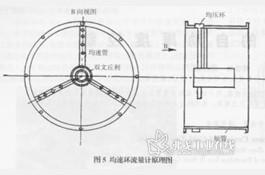
4 average speed loop flowmeter (Figure 5): A patented product for the shortcomings of the constant pressure tube flowmeter that has been applied for more than 30 years, has a small output differential pressure, low accuracy, neglected tube diameter has an impact on the accuracy and other shortcomings . It measures the low pressure by the double Venturi tube, increases the output differential pressure, fully reflects the flow velocity distribution in the tube and other measures with a number of average velocity tubes, improves the technical characteristics of the equalizer tube, and is causing the domestic and foreign manufacturers and users to attention.
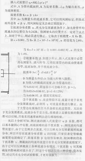
3 Factors Affecting Accuracy
4 Summary 1. Measurement of large-pipe gas flow is still a more confusing issue for the engineering community. In addition to the insertion method described in this article, there are ultrasound, elbow and so on. From the perspective of industrial control systems, line-rate (or surface-speed) plug-in meters are cost-effective, but they are not suitable for accurate metering and trade settlement.
2. Most of the flow meters are faced with a calibration problem. Some people have proposed to verify in the wind tunnel, and others have proposed to verify the full development of turbulence. The question is whether the large pipeline site can provide the above two kinds of flow fields. If it cannot be provided, whether the verification is meaningful and how to solve this problem? The author will elaborate on this issue.
Welded wire mesh is made of high-quality low-carbon steel wire row welding, and then cold plating (electroplating), hot plating, PVC coating and other surface passivation and plasticization treatments.
It achieves
· smooth surface
· uniform mesh
· firm solder joints
· Stability
· good weather resistance
· and good corrosion resistance
Welded wire mesh is also called external wall insulation wire mesh, galvanized wire mesh, galvanized welded wire mesh, steel wire mesh, row welded wire mesh, butt welded wire mesh, construction mesh, external wall insulation mesh, decorative mesh, wire mesh, square mesh, screen mesh, anti-cracking net.
Welded Wire Mesh,Galvanized Welded Wire Mesh,Stainless Steel Welded Wire Mesh,Green Welded Wire Fence
HEBEI JUNTAN METAL PRODUCTS CO., LTD. , https://www.juntanwiremesh.com