![<?echo $_SERVER['SERVER_NAME'];?>](/template/twentyseventeen/skin/images/header.jpg)
The main models for this paper are the gas-steam combined cycle generating units consisting of GE, Siemens, and Mitsubishi's plant-level gas turbines and the gas turbines that have been introduced into the country. The typical projects are Wangting Power Plant and Shenzhen East respectively. Power plant and Zhengzhou Gas Turbine Power Station.
I. Each unit of Wangting Power Plant is a single-shaft F-class gas turbine, three-pressure reheat non-combustion heat recovery boiler and condensing steam turbine. Among them, gas turbines and condensing steam turbines are co-produced by Harbin Power Equipment Co., Ltd. and GE Corporation, and waste heat boilers are produced by Hangzhou Boiler Works.
1.1 Control System and Communication Network The control system mainly consists of a decentralized control system (DCS), a MARK-VI control system provided by a random island master, and a thermal system auxiliary control device. DCS adopts the Ovation system produced by EMERSON of the United States. The MARK-Vl control system of the aircraft is provided by GE of the United States.
1.1.lDCS
The combined cycle unit and its auxiliary systems of the power plant are all unit systems, and each set is equipped with a set of DCS. It is mainly used for the monitoring and control of waste heat boilers and thermocycling systems of gas-steam combined cycle units, electrical generators and generators, high-voltage start-up/standby transformer side breakers, and 6 kV side switches, and realizes gas-steam The data collection, processing, display, alarm, tabulation and performance calculation of the combined cycle unit completes the automatic control and adjustment of all the operating parameters of the gas-steam combined cycle unit to meet the safe and reliable operation of the unit under various load changing conditions. No DCS public network segment and public DCS are provided, and the equipment of the public systems of the two units are respectively connected to DCSs of #1 and #2 units.
Detection of wall temperature and flue gas temperature of waste heat boiler EMERSON's 848T temperature transmitter and 3420 field interface modules are used to form the DCS remote I/O control station for data acquisition and connected to the gas-steam combined cycle unit DCS via a communication cable To achieve centralized monitoring and management.
The combined cycle unit DCS and the gas turbine control system are connected via dual redundant switches using an Ethernet communication interface with TCP/IP to implement two-way communication. Important interlocking protection signals are hard-wired.
1.1.2 Gas Turbine Control System The gas turbine control adopts the SPEEDTRON CMARK-Vl three-redundant microprocessor control system. 3 independent and identical controllers
contain In addition
An Food And Beverage Filter Press is a tool used in separation processes, specifically to separate solids and liquids. The process uses the principle of pressure drive,[clarification needed] as provided by a slurry pump. Among other uses, filter presses are utilized in marble factories in order to separate water from mud in order to reuse the water during the marble cutting process.
Concept Food And Beverage Filter Press Technology
Generally, the slurry that will be separated is injected into the center of the press and each chamber of the press is filled.[1] Optimal filling time will ensure the last chamber of the press is loaded before the mud in the first chamber begins to cake. As the chambers fill, pressure inside the system will increase due to the formation of thick sludge.[2] Then, the liquid is strained through filter cloths by force using pressurized air, but the use of water could be more cost-efficient in certain cases, such as if water was re-used from a previous process.
History
The first form of filter press was invented in the United Kingdom in 1853, used in obtaining seed oil through the use of pressure cells. However, there were many disadvantages associated with them, such as high labour requirement and discontinuous process. Major developments in filter press technology started in the middle of 20th century. In Japan in 1958, Kenichiro Kurita and Seiichi Suwa succeeded in developing the world's first automatic horizontal-type filter press to improve the cake removal efficiency and moisture absorption. Nine years later, Kurita Company began developing flexible diaphragms to decrease moisture in filter cakes. The device enables optimisation of the automatic filtration cycle, cake compression, cake discharge and filter-cloth washing leading to the increment in opportunities for various industrial applications.
Our proven Food And Beverage Filter Press ensures consistent lot-to-lot quality, regulatory compliance, energy management, waste management and cost control for your filter press operations.
The control system network IONET is a network based on Ethernet for communication between the three control modules, the three parts of the protection module and any expansion modules. The unit-level data highway (UDH) is based on an Ethernet network and provides peer-to-peer communication between the steam turbine and generator controls. Data on the network can be transmitted unicast, multicast or broadcast to an equal control system. Plant Level Data Highway (PDH) is used for data communication with power plant DCS or other third party platforms.
Electronic devices are modular. Control, protection, and communication between any expansion module and operator interface Over Ethernet, a real-time, multitasking operating system with floating-point data is provided.
The system has a fault-tolerant control structure that can reliably "vote" inputs and outputs without any single point of failure. The voting value input for each dry contact and the intermediate value for each analog input are calculated in one control module, and the control parameters for application software synthesis are enabled. If any of the three input values ​​are found to be inconsistent, the diagnostic algorithm monitors these inputs and initiates a diagnostic alarm. Each dry contact input is assigned a time tag of 1 millisecond to provide a built-in monitoring of the event sequence (SOE).
The operator interface consists of the GE Fanuc CLMPLICTYR graphics display system and the Microsoft Windows NT operating system PC.
Input/Output (I/O) interfaces directly to the equipment on turbines and generators, such as directly connected to vibration sensors, flame detectors, LVDTs, magnetic speed probes, thermocouples, thermal resistors, ensuring SPEDTRONlCMarkVl diagnostics directly monitors mechanical equipment The normal condition of the probe.
1.1.3 Turbine Control System Turbine control uses a SPEEDTRON CMARKVl triple redundant (TMR) microprocessor turbine control system. 3 separate and identical processors And For monitoring redundant sensors and voting in all important control functions. Protection module
The operator interface consists of the GE Fanuc CLMPLlClTYR graphics display system and the Microsoft Windows NT operating system PC.
SPEEDTRONlCMarkVl and other GE control devices communicate over the peer layer through UDH. Other GE control devices include generator excitation systems, gas turbine static starters. UDH is a dual redundant network. HMl operator interface isolates UDH and PDH.
MARK-VI and DCS use one Ethernet communication interface with TCP/IP, and use GSM for plant level alarms and events with local time tag data transmission.
1.1.4 Backup hard-wired operation There is a small number of backup operation buttons on the main control console of the central control room for emergency shutdown of the unit and protection of the equipment, including: entrance of the pressure control station inlet valve, outlet of the pressure regulation station exit to the burning valve off valve , Stopped Steam Engine (Double Button), Vacuum Break Valve, Diesel Generator Start.
1.2 Control System Function The control level of the combined cycle unit is divided into function group level and sub-group level. All devices in the function group and sub-group level can realize the start and stop control in sequence. The control system has an automatic power generation control (AGO) interface, but currently it can only be controlled manually.
1.2.l DCS Functions DCS's main functions are: Data Acquisition (DAS), Analog Control (MCS), Sequence Control (SCS), Turbine Bypass Control (BPC), Unit Protection and Interlocking, DCS Coordinating Gas Turbine, Residual Heat The operation of boilers, bypass systems, turbines and their auxiliary engines respond quickly, accurately and stably to load instructions for efficient production.
1.2.2 MARK-Vl control system function The MARK-Vl control system integrated with the random island provides complete monitoring, control and protection for the gas turbine and turbo-generator. Its functions are: control, sequence control and protection.
(1) Gas turbine MARK-VI control functions The main controls of the gas turbine include: speed and load control; temperature control; inlet guide vane control and fuel stroke control.
The main sequence of the gas turbine includes: starting device power-on; ignition; starting device disengagement and power-off; accelerating to the same period of speed; adjusting the speed for the same period; automatic and manual synchronization; lifting load; unloading; shutdown; deceleration / automatic car; Purge.
The main protections of gas turbines are: overspeed; over-temperature; vibration; flame detection; emergency shutdown and lubricating oil.
(2) Turbine MARK-Vl control functions The main controls of the turbine are: steam flow control and exhaust steam temperature control.
The main sequence controls of the turbines are: start-up, operation and shutdown;
The main protections of steam turbines include: speeding; low condenser vacuum; large vibration; large wear of thrust bearings;
1.2.3 Main features of the control system The control system's control processor, communication bus, and power supply are all redundantly configured. A single component failure in the system will not cause the failure of the entire control system, nor will it affect the normal operation and protection of the unit. Features.
Hard-wired backup operating equipment is independent of the control system. When the control system has a global health or major failure (such as communication failure, power disappearance, all operator station failures, etc.), ensure that the entire unit can be safely and safely shut down.
1.2.4 Configuration and Configuration of Control Equipment The configuration diagram of the control system of the Wangting Gas-fired Power Plant combined cycle unit is shown in Figure 1. 
Second, the overall planning and construction of the eastern power plant in Shenzhen will involve the construction of nine gas-steam combined cycle generating units. The first phase of the 3×350 MW unit has been completed. The configuration of each unit is a single-shaft F-class gas turbine, three-pressure, reheat, no-combustion, horizontal natural circulation waste heat boiler and condensing steam turbine. Among them, gas turbines and condensing steam turbines are co-produced by Dongfang Electric Group and Mitsubishi Corporation, and waste heat boilers are produced by Hangzhou Boiler Works.
2.1 Control System and Communication Network The power plant control system mainly includes the DCS, the control system provided by the random island main equipment and the auxiliary equipment control equipment of the thermal power system. DCS uses the products of the Ovation system from EMERSON, USA. The island's control system uses Japan's Mitsubishi's DIASYS products.
2.1.1 DCS
The combined cycle unit and its auxiliary systems are all unit systems. Each unit uses one set of DCS. It is mainly used for monitoring and control of the waste heat boiler and its auxiliary systems, thermal systems, and plant power supplies, and is also compatible with the gas turbine control system. The two-way redundant communication is carried out. The operating personnel can realize centralized monitoring and control of the entire combined cycle unit through the man-machine interface of the DCS in the centralized control room.
The basic settings of DCS are: unit unit DCS + public DCS network, the monitoring of the public system can be completed at the unit unit operator station, and the operation of the 3 unit unit operator station to the public system is safety blocked, and the 3 unit unit operators station are All screens of the public network can be displayed, but only one unit crew operator station can control the public system at the same time.
The DCS communication network is divided into two layers: the unit process monitoring level and I/O level. The unit process control level is a Fast Ethernet communication network with a communication rate of 1 OOMb/s. This network is mainly used for communication of DCS control stations, operator stations, printers, and other equipment, and is connected to the entire plant SIS network. The I/O level network is a PCI bus distributed in various process control stations with a communication rate of lOMb/s. This level of network bears all I/O modules in the same station.
2.1.2 Gas Turbine Control System The gas turbine control is based on the Mitsubishi DlASYS (TCS+PCS+TPS) system. The TCS Turbine Control System mainly completes the monitoring and control of the turbine-turbine-generator body; the PCS Process Control System mainly completes the turbine bypass system, the turbine shaft sealing system, and the condenser vacuum system. Monitoring and Control; TPS Island Protection System (turbine protection system) mainly completes the protection of gas turbine-generator.
2.1.3 Backup Hard-wired Operation Backup hard-wired operations configured by DCS console include: unit tripping, generator stopping, power generation and transformation group shutdown, AC oil pump startup, DC oil pump startup, vacuum breaker door opening, high, medium and low pressure opening. Emergency water release gate, diesel generator set start-up, and pressure shut-off station fire alarm shut-off valve. These backup hard-wired operations ensure safe shutdown of the unit in emergency situations.
2.2 Control System Function 2.2.l DCS Function The DCS control function setting of the power plant is similar to that of Wangting Power Plant.
2.2.2 TCS+PCS+TPS Functions The main functions of TCS are:
(1) Gas turbine control functions: including ALR "automatic load adjuster", speed control, load control, temperature control, fuel limit control, minimum selection control, fuel flow control, inlet guide vane (IGV) control, combustion chamber bypass Valve control.
(2) Turbine control functions: including HP/IP/LP steam pressure control, OPC (overspeed protection control), ST test function.
The main functions of PCS are:
Turbine bypass control, turbine bypass temperature control, shaft seal steam pressure control, shaft seal steam temperature control, ST exhaust valve control.
The main functions of TPS are:
Gas turbine / turbine protection are: gas turbine - turbine speed, large axial displacement, large shaft vibration, low oil pressure, low fuel pressure, high smoke pressure, combustion chamber flame disappear, manual shutdown, waste heat boiler trip , TCS failures and other trips.
2.3 The main features of the control system set up a "one-click start and stop" function (APS), also known as the power plant automatic control system. In theory, APS can complete all automatic start-up processes from vacuum to full load and all automatic stop processes from full load to unit stop.
The unit's overall start/stop routine is divided into breakpoints, each of which is displayed on the LCD. The operator can monitor the running status of the unit through the LCD, and the operator can choose whether to execute from 1 breakpoint to the next breakpoint, or manually intervene in the start-stop process of the unit to achieve semi-automatic start and stop operation of the unit.
The main breakpoints of the start-up process: vacuum, start-up of waste heat boilers, start-up of steam turbines, synchronization and load increase.
The main break point in the shutdown process: the turbine stops, the waste heat boiler stops, and the vacuum breaks down.
2.4 Configuration and Configuration of Control Equipment The control area of ​​the combined cycle unit of the Eastern Gas Power Plant in Shenzhen is shown in Figure 2. 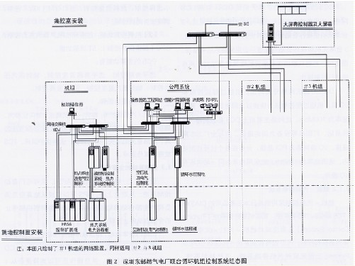
3.1 Control System and Communication Network The power station control system is mainly composed of two parts: DCS and TCS. All of them adopt the TelepermXP system manufactured by Germany's Siemens AG and integrated design.
3.1.1 Distributed Control System DCS is embedded in the TelepermXP system and has the following subsystems: (1) The analog adjustment system (MCS), which mainly completes the coordinated control of the unit and the regulation control of the waste heat boiler, high pressure bypass, etc.; (2) sequential control The system (SCS) mainly completes the sequential control of the unit level (APS, Siemens called SGCUNlTCOORDlNAT5lON), the sequential control of the waste heat boiler and the BOP system; (3) the waste heat boiler protection system; (4) the data acquisition system (DAS) to complete the monitoring Control and data collection and management; (5) Electrical quantity control (ECS, G&A), mainly to complete the monitoring of the electrical quantity of the power generation and transformation unit and the monitoring of the power system and the utility power system of the unit.
The air compressors and natural gas pressure control stations of public systems are integrated into the DCS control system and are connected to the public system DCS. The chemical water treatment and auxiliary boilers are connected to the public system DCS by means of communication.
3.1.2 Gas Turbine Control System The gas turbine control system TCS (TelepermXP) is supplied by the main equipment manufacturers and integrated with the DCS (TelepermXP) system. It is located in the unit network.
The gas turbine can be divided into a main control system and a protection system functionally, and the two are inseparable overall. In normal operation, the main control system runs according to the program parameters required by the gas turbine generator set. When a fault occurs, the protection system sends out an alarm signal to remind the operator to eliminate the fault and return to the safe operation state; when there is a major fault, the protection system Interrupt the gas turbine to ensure the safety of the unit. The AP automatic processor in the main control system mainly collects various parameters such as temperature, pressure, vibration, etc., starts and stops the gas turbine program, gas, natural gas, frequency control, boiler purging, and generator body data acquisition. Functions such as control and control; APT in the main control system mainly performs combustion engine exhaust temperature control, start control, fuel control, load limit control, overspeed control, compressor inlet pressure limitation, and the like. Each system outputs a fuel supply reference based on different operating phases. These fuel supply references make a minimum selection and the minimum value serves as an execution command signal. At the same time, only the smallest fuel reference is in effect. By changing the fuel reference, the speed and load of the unit are controlled. By changing the compressor inlet steerable leaves, controlling the turbine exhaust temperature and preventing surge. The protection system is divided into two parts, the conventional part is completed by the AS620 (including the trip signal from the APT through the network), and the fast part is completed by the AG95F (signal and processor are redundant structures), in which the trip signal in the AS620B is output to In the AG95F system, the AG95F system outputs the total trip signal and completes the emergency shutdown of the unit. The signal transmission between AS620B and AG95F is done through the network.
The control range of the steam turbine is: steam turbine body, clutch, turbine auxiliary system. The turbine auxiliary systems included in the TCS control are: (l) Turbine Control Oil System; (2) Lubricating Oil System (Common Fuel Supply System for Gas Turbines and Generators); (3) Steam Seal System, Door Rod Leakage System; ( 4) Condenser system; (5) Turbine seal water system; (6) Vacuum system (7) Bypass system.
The design of the unit automation system has a high starting point. To meet the requirement of two-shift operation of gas-fired power plants and meet the requirements of quick start and stop of the unit, the unit-level sequential start/stop function is designed to achieve one-button operation.
Teleoperation of the TelepermXP system uses a client/server structure. The unit sets redundant data server (PU) pairs. The operator station exchanges data with the controller through the server (PU). The engineer station can access the server. Can directly access the control station. The system uses a three-level network connection; (1) The monitoring operation-level network (TerminalBus) adopts a CSMA/CD-based Ethernet OOMbs/s virtual ring network, which is connected to the server through the process control level network, through the OfficeLan and external systems on the OPC server. (SIS) connected. (2) The process control level network PlantBus) adopts a 1OMbs/s virtual ring network, and is connected to the main control unit (APT/AP) in a node manner. (3) Fieldbus layers (FBUs) use 1.5 Mbs/s Profibus DP field bus to connect to I/O modules.
1# unit unit DCS, 2# unit unit DCS and public DCS have their own independent ring networks. The common system ring network is connected to the 1# and 2# unit unit networks through the network interface (Link).
The complete set of control software for the unit is used by a combination of child software. The upper monitoring system uses the monitor software of TelepermXP system 0M650 to perform integrated monitoring of the entire unit. The engineer station uses TelepermXPES680 engineering tool software, the lower control DCS, gas turbine and turbine auxiliary system, uses the TelepermXPAP620 function control software, the gas turbine and the turbine body use DigitalControlSystemSIMADYND function control software, DCS and TCS communicate through the process control level network (PlantBus).
3.1.3 Backup Hard-wired Operation Backup hard-wired operations of the central control room master console include: total plant fuel tripping, gas turbine emergency tripping, steam turbine emergency tripping, generator-transformer tripping, lubricating oil pump startup, and generator de-magnetizing switch Trip.
3.2 The main characteristic of the control system The integrated design of DCS and TCS, TelepermXP is based on the structure of Profibus DP field bus, DCS is further decentralized.
According to different functions, the closed-loop control, open-loop control and protection operation of the unit set up three subsystems, SimadynD, S5-95F, AP.
3.3 Configuration and Configuration of Control Equipment The configuration diagram of the control system of the combined cycle unit of Zhengzhou Gas-fired Power Plant is shown in Figure 3. 
4.2 Self-starting and stopping function of the unit needs to be tested in practice There are still different views on setting up the self-starting and stopping system for gas-steam combined cycle units in gas-fired power plants. It is not difficult to design the unit to start and stop the system, but there are many problems that need to be studied in order for the system to function properly. In particular, the controllability of the main and auxiliary engines of the combined cycle unit has yet to be solved. The 2×3OOMW combined cycle unit of Wangting Power Plant, the 3×35OWM combined cycle unit of Shenzhen East Gas Power Plant, and the 1×35OMW combined cycle unit of Beijing No. 3 Thermal Power Plant all have a self-starting and stopping system, but there is no commissioning or Not officially activated. Since the start-stop of the unit belongs to the coordinated control range of the power plant, it issues commands to command the relevant systems (or functional groups) of the local automatic control level, and the related systems have been set on the LCD screen of the DCS operation station. According to the help screens with detailed display and operation methods, the operating personnel can grasp the working conditions of these functional groups at any time and issue command instructions to them in a timely manner. In order to put the unit into production as soon as possible, there is currently no serious inspection of the unit's self-start/stop function. Therefore, whether the specific project is set to start and stop the unit should be combined with the actual situation to determine.

Specifications
Parameters
Units
Scale
1-100
m3/h
Operation
Batch, Continuous
Objectives
Clarification, Solids Recovery
Slurry settling characteristics
Rate
<0.1 to >5
cm/s
Clarification
Poor
Proportion of sludge
< 2% vol to > 20% vol
Slurry filtering characteristics
Slow at the rate of cm/h, up to 10 h
Food Beverage Sewage Treatment,Automatic Sewage Filter Press,Filter Press With Belt Convery For Food Beverage
Hebei TianGuan Filter Press Co., Ltd. , http://www.filterpressure.com