1 inverter static test results to determine the fault
First of all, we can do a static test on the inverter. The general-purpose inverter roughly consists of the following parts: (1) rectifier circuit; (2) DC intermediate circuit; (3) inverter circuit; (4) control circuit. Static test is mainly a rectifier circuit, DC intermediate circuit and inverter circuit part of the high-power transistor (power module) of a test tool is mainly multimeter. Rectifier circuit rectifier diode is mainly a positive and negative test to determine its good or bad, of course, we can also use the pressure gauge to test. DC intermediate circuit is mainly the capacitance of the filter capacitor and pressure measurement, we can also observe whether the safety valve on the capacitor burst, whether there is leakage phenomenon to determine its good or bad. Judgment of the quality of the power module is mainly to judge the freewheeling diode in the power module. For the IGBT module we also need to determine whether the trigger voltage can be turned on and off.
2 through the inverter display to determine where the fault point
(1) OC. Overcurrent fault
This is probably the most common failure in the drive. We must first rule out the fault caused by the parameter problem. For example, the current limit, acceleration time is too short may cause over-current generation. Then we have to decide if there is a problem with the current sense circuit. To FVR075G7S-4EX as an example: We sometimes see FVR075G7S-4EX not connected to the motor when the panel will have current display. Where is the current coming from? At this time we must test its three Hall sensors, in order to determine the phase of the sensor damage, we can open a time for each phase of the sensor to see if there will be over-current display, after such tests can basically ruled out OC fault.
(2) OV. Over voltage fault
We must first rule out the fault caused by the parameter problem. For example, the deceleration time is too short, as well as due to regeneration load caused by overvoltage, etc., and then we can look at the input voltage is a problem, and finally we can look at the voltage detection circuit fails, the general voltage detection circuit voltage sampling Point, are the voltage of the intermediate DC circuit. Take Sanken SVF303 as an example, after it is sampled by the DC loop (about 530V DC), it is isolated by the optocoupler after it is bucked by a larger resistance. When the voltage exceeds a certain value, "5" overvoltage This machine is digital tube display) We can look at the resistance of oxidation variability, optocoupler whether there is a short circuit and so on.
(3) UV. Under voltage
We can first look at the input voltage whether there is a problem, and then look at the voltage detection circuit, fault diagnosis and overvoltage the same.
(4) FU. Fast fuse failure
In the current launch of the inverter mostly introduced fast fault detection function. (In particular, high-power inverter) to LG030IH-4 inverter, for example. It is mainly on the back of the fast melt front voltage sampling test, when the fast-melt damage will inevitably occur after the fast-melt voltage is not isolated optocoupler action at this time, there FU alarm. Fast melt replacement because it can solve the problem. In particular, it should be noted that before replacing the fast melt must determine whether there is a problem with the main loop.
(5) OH. Overheating
The main cause of the inverter internal heat is not good. We can check the cooling fans and ventilation channels.
(6) SC. Short circuit fault
We can detect if there is a short circuit inside the inverter. We Yaskawa 616G5A45P5, for example, we test the internal lines, may not necessarily have a short circuit, then we can detect the power module may have a problem, the drive circuit is normal, the replacement of the power module should be able to repair the machine .
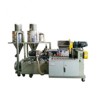
LINA Pelletizing-cooling Integrated Machine
LINA Pelletizing-Cooling Integrated pelletizing line centralizes all functions of a complete granulation line on one independent working platform. The pelletizing efficiency is 1-2 times higher than traditional masterbatch pelletizing production line. With the combination of PLC control system, LINA pelletizing-cooling integrated machine makes the granulation process easier, the working area smaller, labor cost lower and maintenance rate lower.

LINA CIM/MIM Twin Taper pelletizer
Twin taper forced feeding is adopted for mixed metal agglomerates, this feeding method is more efficient than traditional double wrist feeding method. Twin taper feeding is stable and feeding materials are uniform, it increases finished particles are uniform and full. This machine is specific for the granulation of high hardness, high strength and abrasion resistance materials, including stainless steel powder, iron powder, magnetic powder, zirconia, ceramic powder etc.
Main features
Oil shower lubrication system.
Material of barrel and screw: 38CrMoALA alloy steel nitride for 72 hours, polished and surface sprayed carbide.
Plunger type pelletizer (non-screw pelletizer): Feeding method of Plunger type pelletizer: hydraulic.
Applicable materials: High - end Inorganic nonmetal like zirconia ceramics.
Applicable to rare earth permanent magnet, magneto-optical, superconducting, hydrogen storage and other rare earth alloys.
Value Points:
1. Automation: Continuous kneading and pelletizing.
2. Eco-friendly: No gas masks needed while operating.
3. User-friendly: Quick release design for die head.
4. Modular: Based on user`s demand, manually material feeding can be updated to automatic weighted feeding.
Pelletizing-cooling Integrated
Pelleting-Cooling Recycling Equipment,Pelleting-Cooling Integrated System,Pelleting-Cooling Integrated Recycling
LINA Machinery Industrial Co.,Ltd , http://www.linakneader.com
![<?echo $_SERVER['SERVER_NAME'];?>](/template/twentyseventeen/skin/images/header.jpg)